Power Adapter Circuit Diagram
If you want to charge 5 to 10 lithium batteries in parallel then this circuit is for you. This conversion process is necessary for most electronic devices, as they usually require dc power to operate. Web an ac adapter circuit diagram is a useful tool in understanding the components, wiring, and overall design of an ac power adapter. Without them, you could be running your valuable electronics at half their potential and could even be putting yourself in danger.
electronic circuit Page 17 Next.gr
12 Volt 10 Ampere DC Power Supply Circuit adapter What is the purpose of all these resistors and capacitors in Schematic Diagram Of A Power Supply How to Make Variable Power Supply
A Circuit Diagram Is Important Because It Not Only Shows The Components And Wiring That Make Up The Circuit, But It Also Shows How They Are Connected Together.
Bench lab power supply 0 50v 5a gadgetronicx. Usb 5v to 1.5v/3v dc adapter ( converts usb to 1.5v or 3v output) In this tutorial, we will learn how to build a 12v smps circuit that would convert ac mains power to 12v dc with a maximum current rating of 1.25a.
Web Power Adapter Schematic Diagrams Are The “Blueprint” For How Electrical Power Is Safely Routed And Transformed From One Device To Another.
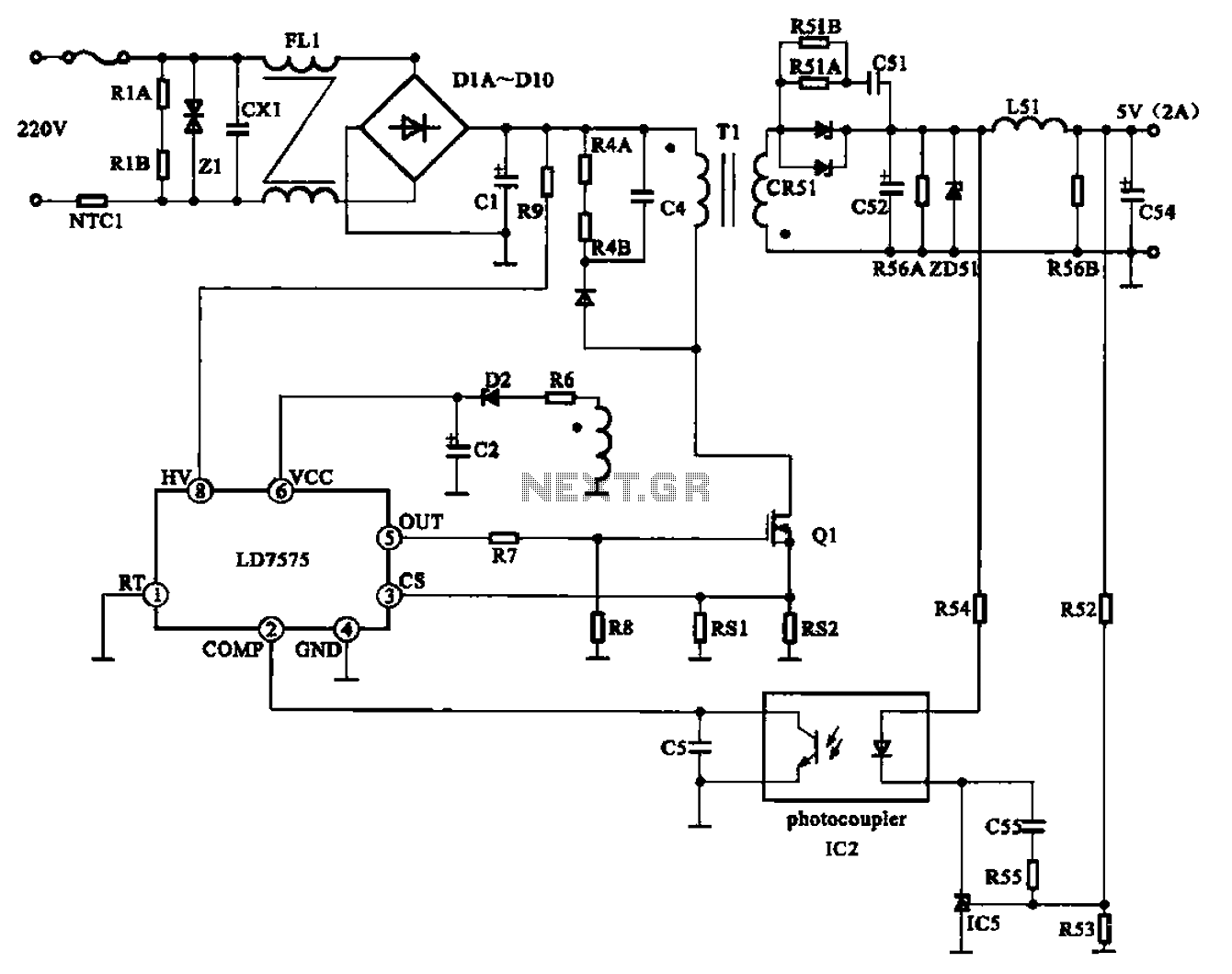
Most household electronic products like mobile chargers, bluetooth speakers, power banks, smart watches etc requires a power supply circuit that could convert the ac mains supply to 5v dc to operate them. This circuit will provide you more than 10amp current at output but you have to use 5 volt 10amp as input. The transformer then steps down the voltage to a level which can be used by the other components.
The Ac Input Provides The Power Necessary To Start The Circuit.
Web these circuits convert alternating current (ac) power from an external power source into direct current (dc) power that can be used by the device's internal components. A 20w, 120vac to 12vdc adaptor. The lm317 is a monolithic integrated ic comes with three different packages and it is a positive adjustable voltage regulator.
Click Here To Download This Circuit Diagram.
12v and 5v output many ideas of 12v and 5v dual power supplycircuit diagram at 3a max; Web here battery charger circuit diagram designed by implementing adjustable voltage regulator lm317 with auto cut off feature. You can use this circuit to charge 12v sla battery or 12v gel cell battery and so on.
In This Tutorial We Will Learn How To Build A 12V Smps Circuit That Would Convert Ac Mains Power To 12V Dc With A Maximum Current Rating Of.
The maximum input power is 20w. 1.5v, 3v, 4.5v, 6v, 9v at 1.5a selector voltage regulator; Web the most commonly used type of power supply circuit is the smps (switching mode power supply), you can easily find this type of circuits in your 12v adapter or mobile/laptop charger.
This Circuit Will Give Adjustable Dc Supply Output And Charges Battery Ranges From 6 Volt To 12 Volt.
12v 1a smps power supply circuit design on pcb. Web 5v 2a smps power supply circuit power supply unit (psu) is a vital part in any electronic product design. Web power adapter circuit diagram datasheet, cross reference, circuit and application notes in pdf format.
Web Other Linear Power Supply Circuit Diagram Fixed Volts Regulator:
Web the most commonly used of type of power supply circuit is the smps (switching mode power supply), you can easily find this type of circuits in your 12v adapter or mobile/laptop charger. Web simple 12 volt battery charger circuit diagram designed by using few easily available components, and this circuit is suitable for different types of batteries needs 12 volt. Such diagrams help electricians, engineers, and technicians to analyze both the physical layout of the circuit as well as its electrical properties.
This Circuit Is Designed To Provide Charging Current Upto 3 Amps And This Circuit Don’t Have.
12v battery charger circuit using lm317 (12v power supply) transformerless power supply; Check our other power supply circuit: Web how to make variable power supply circuit with digital control.
Web An Ac Adapter Circuit Diagram Is A Blueprint For An Electric Circuit That Is Used To Power A Device Such As A Laptop, Tablet, Charger, Or Any Other Device That Requires Ac Power.
This power supply operates from a universal input to provide a 19 v, 65 output capable of operation in a sealed enclosure at an ambient temperature of up to 40 °c. Web we have shown the motor rotation in both the directions, using this dual power supply circuit, in the video below. Web high current lithium battery charger circuit diagram with mosfet.
12V 1A Linear Regulator Using Transistor And Zener Diode;
We talked about adapters, adapter circuit diagram, what is an adapter, and how does and adapter works. Web in this video we talked power supply circuits and adapters schematic diagram. Web a basic power adapter circuit consists of an ac input, a transformer, capacitors, a diode, an inductor and an output.
Electrical Circuit Diagram Of The.
The schematic diagram of the circuits and how to implement them for our design is presented in this article. 9 ways to build 24v power supply circuits with easy parts. Circuit design schematic of adjule voltage regulated power supply.